Both applications are independent and run autonomously. The flow of data is a unidirectional diagram:
Process Data -> PLC -> Visor_On -> Database -> Visor
The typical structure of data acquisition using "VISOR" is shown in Figure 1-1.
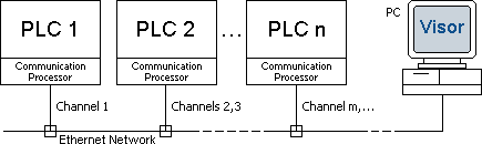
Figure 1-1. The typical structure of data acquisition
The workstation (PC) with installed and configured software "VISOR" connects to an automation system (PLC) using "Ethernet" network.
Detailing of historical data (sampling frequency) is dependent on the network performance. But for a certain of data, "VISOR" provides a reading of the data synchronously with the cycle of PLC program (every cycle), in the "SYNCHRONOUS" mode.
Software "VISOR" can be installed on IBM-compatible personal computer (PC) with the recommended minimum configuration:
- CPU Pentium IV 1600 MHz;
- 1024MB RAM;
- hard disk 100GB;
- video with a resolution 1024x768, RAM video 16MB;
- Ethernet Network card.
Operating systems supported "VISOR":
- Windows 2000 Pro/Server;
- Windows XP;
- Windows 2003 Server;
- Windows 7.
Supported types of PLC:
In order to communication server Visor_On could read the required data, they must be pre-prepared in PLC. To do this you have to create the data block in PLC and to provide recording of necessary variables.
Data is read in parts, the maximum size of them - 2048 bytes. To read the part of data from the PLC communication server Visor_On uses the channel. Channels are Independent, each channel individually configurable. For each PLC can be one or more channels, due to this proportionally increase the size of the read data. The maximum number of channels is 30 (depending on license). Thus the communication server can read up to 61440 bytes data, while the number of PLC can reach 30.
The main variants for acquisition and analyzing of data presented in the block diagram shown in Figure 1-2.
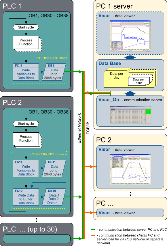
Figure 1-2. Variants for acquisition and analyzing of data
"VISOR" supports 3 modes of read data from the PLC:
- TIMESLOT - with a fixed period of samples;
- TIMESLOT_SIMPLE - with a fixed period of samples, simplified;
- SYNCHRONOUS - synchronous with the PLC scan cycle.
1.3.1. The "TIMESLOT" mode
This is a direct reading of the data. For the "TIMESLOT" mode the data block, in addition to variables, should have the header that contains the time of PLC clock. This time can be obtained using standard functions of the processor (CPU). Time format in the header of the data block coincides with the “DATE_AND_TIME” data type of PLC SIMATIC S7.
Communication server Visor_On periodically, at regular parametrized intervals, reads the data from the PLC and stores them in the database of historical data on the workstation (PC). The period of reading data is selected on the basis of the desired detail. If the PLC is not able to provide data within a specified time interval, the period of reading increases automatically. Usually in this mode is not possible to reach the highest of detail (read data every program execution cycle), because it requires high bandwidth data transfer, which sometimes is not physically possible. This mode should be used if you do not need to write fast changing variables.
The flow of data in this mode:
Process Data -> PLC data block -> Visor_On -> Database
Advantages of the "TIMESLOT" mode:
- easy to use and configure;
- does not require any additional software in the PLC.
Disadvantages of the "TIMESLOT" mode:
- low detailing values of variables for fast programming cycles, when the PLC scan cycle time much less than data reading period;
- reducing of the period of reading data from the PLC imply increasing load on network equipment.
1.3.2. The "TIMESLOT_SIMPLE" mode
This is the easiest mode of data collection. The "TIMESLOT_SIMPLE" mode differs from "TIMESLOT" so that a time of each data block reading is taken from internal workstation (PC) clock. In this mode the header of the data block containing the time of PLC clock is not required.
Advantages of the "TIMESLOT_SIMPLE" mode:
- same as in the "TIMESLOT" mode.
Disadvantages of the "TIMESLOT_SIMPLE" mode:
- same as in the "TIMESLOT" mode.
- as being the time is used from internal workstation (PC) clock, it is some mistiming between real time of data changes and time of receiving them, this shift occur because there is the delay of data transporting through the network, which is variable.
1.3.3. The "SYNCHRONOUS" mode
In this mode data is read not directly from the data block containing variables, but from the data block of the circular buffer. Filling the circular buffer occur synchronously with the PLC scan cycle by using a special software written on the language of used PLC. The flow of data in this case is as follows:
Process Data -> PLC data block -> PLC buffer data block -> Visor_On -> Database
Thanks to the use the buffer there is no need to read data from the PLC often, thus reducing load on network equipment. In addition, the buffer allows reading of data synchronously with the scan cycle of the program PLC (each cycle). Performance of this mode depends on:
- throughput and the load of PLC communication processor;
- number of variables (data size);
- rate of change of variables.
Table 1-1 shows examples of the "SYNCHRONOUS" mode performance for PLC S7-400 at different times of the program execution cycle. The variables are read in each cycle.
Table 1-1. Examples of the "SYNCHRONOUS" mode performance
PLC cycle time,
msec |
Data changes frequency |
Buffer size in PLC,
KBytes |
Periodicity of buffer reading from PLC,
msec |
Read data size,
Bytes |
Data flow,
KBytes/sec |
| 2 |
every cycle |
16 |
500 |
40 |
~ 18 - 20 |
| 2 |
every 5th cycle |
16 |
500 |
200 |
~ 16 - 18 |
| 10 |
every cycle |
16 |
500 |
200 |
~ 16 - 18 |
| 10 |
every 10th cycle |
16 |
1000 |
1000 |
~ 8 - 10 |
| 20 |
every cycle |
16 |
500 |
400 |
~ 8 - 9 |
| 20 |
every 10th cycle |
16 |
1000 |
2000 |
~ 4 - 5 |
Advantages of the "SYNCHRONOUS" mode are obvious:
- synchronism between data changing and data reading (reading synchronously with the PLC scan cycle);
- guaranteed maximum detail of variables values;
- low load on network equipment.
Disadvantages include:
- require additional memory for the circular buffer in PLC.
Attention! The "SYNCHRONOUS" mode is more perfect and it is recommended for a priority using.
|